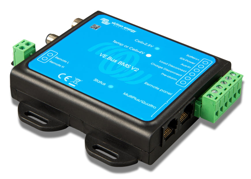
Consumers have a fourteen-day withdrawal.
Note: Please register your revocation by email before returning. You will then receive information from us for return.
Right of withdrawal
You have the right to revoke this contract within fourteen days without giving reasons.
The cancellation period is fourteen days from the day on which you or a third party named by you, who is not the carrier, have or has taken possession of the last part of the part or the last piece.
In order to exercise your right of cancellation, you must (Frenchman GmbH, Südstraße 40, 49084 Osnabrück, Mail@frenchman-energy.eu, Germany) by means of a clear explanation (e.g. a letter sent by post or email) Decision to revoke this contract. You can use the attached model cancellation form, but this is not prescribed.
To maintain the cancellation period, it is sufficient for you to send the notification to the exercise of the right of cancellation before the cancellation period expires.
Consequences of the revocation
If you cancel this contract, we have all payments that we received from you, including the delivery costs (with the exception of the additional costs, which result from the fact that you choose a different type of delivery than the cheapest standard delivery offered by us to repay), immediately and at the latest within fourteen days from the day, on which the notification of your revocation of this contract was received. For this repayment we use the same means of payment that you used in the original transaction, unless something else has been expressly agreed with them; Under no circumstances will you be charged for fees for this repayment. We can refuse the repayment until we have returned the goods or until you have provided the proof that you have returned the goods, depending on which the earlier time is.
You have the goods to send back to us immediately and in any case within fourteen days from the day on which you inform us about the revocation of this contract. The deadline is preserved if you send the goods before the deadline of fourteen days. They bear the immediate costs of returning the goods. In the case of goods that cannot be returned normally due to their nature, these are EUR 49. You only have to pay for any loss of value of the goods if this loss of value is due to the quality, properties, properties and functioning of the goods not necessary to deal with them.
- The right of withdrawal does not exist with the following contracts:
- Contracts for the delivery of goods that are not prefabricated and for the production of which an individual selection or determination of the consumer is decisive or which are clearly tailored to the personal needs of the consumer.
(If you want to revoke the contract, please fill out this form and send it back.)
- To Frenchman GmbH, Südstraße 40, 49084 Osnabrück, email address: mail@frenchman.eu
- hereby revoked (n) I/we (*) the contract concluded by me/us (*) contract for the purchase of the following goods (*)/The provision of the following service (*)
- ordered on (*)/receive on (*)
- Name of the consumer (s)
- Address of the consumer (s)
- Signature of the consumer (s) (only when notifying paper)
- Date
(*) Incorrect painting.
special instructions
If you finance this contract through a loan and cancel it later, you will no longer be bound by the loan contract, provided that both contracts form an economic unit. This can be assumed in particular if we are your lender at the same time or if your lender uses the financing of our participation. If we have already received the loan if the revocation has been effective, your lender will enter our rights and obligations from the financed contract in relation to you in relation to the legal consequences of cancellation or return. The latter does not apply if the present contract has the acquisition of financial instruments (e.g. securities, foreign exchange or derivatives). If you want to avoid a contractual commitment as much as possible, make use of your right of withdrawal and also revoke the loan contract if you are also entitled to a right of withdrawal.

